5 minutes
VPLS with OpenBSD
VPLS is extremely useful in allowing multiple sites to be connected to a single bridged domain. Unfortunately, VPLS networks are typically implemented with proprietary technology like a Cisco router. OpenBSD lets us break free of the typical restrictions of proprietary technology and use 100% free software to make a full-fledged VPLS network.
Why VPLS?
With VPLS, you can deliver a layer 2 circuit over a routed backbone. This lets you extend that circuit from one location to another over a route that you can easily control. If the backbone is not routed, you leave the path-finding up to spanning tree; while that works for smaller networks, the bigger your layer 2 domain gets, the less-reliable spanning tree gets. Eventually, it may start taking spaghetti-like paths, and there will be little you can do about it.
VPLS is also useful in allowing the extension of layer 2 domain to a remote site. For example, in the case of VoIP phones, VPLS would allow the phones to be directly connected to the remote VoIP server, requiring no configuration whatsoever at the client site.
VPLS on a High Level
VPLS works by creating MPLS pseudowires (point-to-point layer 2 circuits) to every node you want to be part of your bridged domain. You then add each pseudowire as well as the physical interface you want to be “bridged into” the VPLS domain. In basic terms, you have now created a “virtual switch,” plugged each pseudowire into it, and plugged your physical interface into it.
The Setup
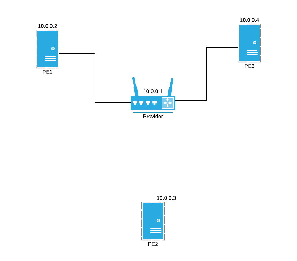
This setup is completely virtualized, but it can be replicated easily with physical servers as well. There will be one provider and three provider edges. Each router will have a unique router-id by which it will be identified in OSPF and LDP. That address will be assigned to a secondary loopback interface (lo1) and advertised to the other routers using OSPF. The setup looks like this:
 {:width="500px”}
Each PE will be directly attached to the provider with a /30. I’m using the 172.30.2.X IP scheme, but you can use whatever you want. Just make sure to match up those addresses between the provider and PE. Similarly, my use of 10.0.0.X for the router-id’s can changed to whatever you want.
Global Configuration
On each of the nodes, you will have to enable some services. I’m doing this in /etc/rc.conf.local. Append these two lines at the bottom to enable OSPF and LDP. Also make sure to wipe any lines disabling OSPF or LDP out of /etc/rc.conf and /etc/rc.conf.local:
ospfd_flags=""
ldpd_flags=""
You’ll also need to give each router its appropriate router-id on its loopback interface. You can put this in /etc/rc.local or use the hostname.XXX format. I prefer the hostname.XXX format.
/etc/hostname.lo1:
inet 10.0.0.1 255.255.255.255
description "id_loopback"
Make sure to change that 10.0.0.X address for each router.
Provider Configuration
The provider is the simplest node to configure since it just acts as a glorified label switch.
/etc/ospfd.conf:
router-id 10.0.0.1

area 0.0.0.0 {
    interface lo1
    interface re0
    interface re1
    interface re2
}
/etc/ldpd.conf:
router-id 10.0.0.1

address-family ipv4 {
    interface re0
    interface re1
    interface re2
}
/etc/hostname.re0:
inet 172.30.2.1 255.255.255.252
mpls
description "p1_edge"
It’s critical that you have the mpls line in your configuration. This lets OpenBSD know to treat that interface as a provider-facing interface. Repeat this interface configuration for each PE. Make sure to use a different IP for each interface as well as a different subnet. I recommend using consecutive /30 blocks (172.30.2.0/30, 172.30.2.4/30, 172.30.2.8/30).
PE Configuration
The configuration of PEs is similar to that of the provider, but pseudowires have to be created to each other PE. Each PE has two physical interfaces. re0 is the provider-facing interface, and re1 is the client-facing interface.
/etc/ospfd.conf:
router-id 10.0.0.2

area 0.0.0.0 {
    interface lo1
    interface re0
}
First, we have to create our pseudowires. These follow the mpwX naming convention. All we have to do in /etc/hostname.XXX is create them and bring them up. LDPD takes care of the rest. We also have to bring up our physical client-facing interface.
/etc/hostname.mpw0:
create
up
/etc/hostname.re1:
up
We also need to bring up our bridge interface and add our pseudowires and our physical interface to it.
/etc/hostname.bridge0:
add re1
add mpw0
add mpw1
up
description "vpls_bridge"
Remember that in this LDP configuration, re0 is provider-facing, and re1 is client-facing. If you want some extra information on how ldpd.conf works, check out the OpenBSD ldpd.conf man page. /etc/ldpd.conf:
router-id 10.0.0.2

address-family ipv4 {
    interface re0
}

l2vpn pe1 type vpls {
    bridge bridge0
    interface re1

    pseudowire mpw0 {
        neighbor-id 10.0.0.3
        pw-id 100
    }
    pseudowire mpw1 {
        neighbor-id 10.0.0.4
        pw-id 100
    }
}
Repeat this process with the rest of the PEs, changing the appropriate IPs and router-id’s. After that’s all done, restart ldpd and ospfd, use /etc/netstart to bring up interfaces, and you’re ready to go!
You can find my full configuration here. Use this if you need any extra help figuring out the configurations for the nodes.
Testing
To test your VPLS setup, connect clients to your physical interfaces on all your PEs, and give them all static IPs in the same subnet. Try to ping each other and see if the pings return. If they do, you did it! You’ve now created a functional VPLS network.
Diagnostics
More likely, however, your network doesn’t work. Don’t worry! OpenBSD has some great tools for viewing LDP status. Here are some common commands and what they look like on a working PE:
pe1 / root / 23:18:29
> ~ # ldpctl show neighbor
AF   ID              State       Remote Address    Uptime
ipv4 10.0.0.1        OPERATIONAL 10.0.0.1        00:03:53
ipv4 10.0.0.3        OPERATIONAL 10.0.0.3        00:03:11
ipv4 10.0.0.5        OPERATIONAL 10.0.0.5        00:03:11
pe1 / root / 23:18:29
> ~ # ldpctl show l2vpn pseudowire
Interface   Neighbor        PWID           Status
mpw0        10.0.0.3        100            UP
mpw1        10.0.0.4        100            UP
You can also use ospfctl to if you think the problem may lie in the routing.
Conclusion
VPLS is some amazing technology, and hopefully, you can implement it yourself with the help of this post.